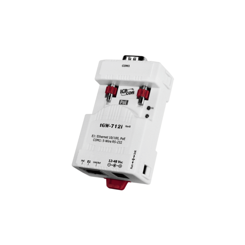
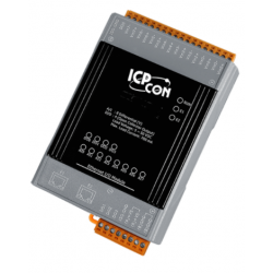
Compact Modbus / TCP for RTU / ASCII Gateway with PoE
must not be programmed
1 x RJ45 10 / 100Mbps
1 x RS232 (DB9 Han)
Supports Modbus TCP / UDP Master and Slave
Supports Modbus RTU / ASCII Master and Slave
Baud Rate Up to 115,200 BPS
Self-Tuner for RS232
IEEE 802.3af - PoE (PD)
Supply voltage U / Poe: 12 - 48VDC 2Watt
Goal: 90 x 52 x 27 mm
DIN bracket
Operating temperature: -25 - + 75 ° C
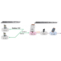
ETH-MODGW7xx series is a Modbus gateway that allows for a Modbus TCP / IP - UDP host to communicate with serial Modbus RTU / ASCII remote terminal units through an Ethernet network, thus eliminating the cable length limitation of legacy serial communication devices . The module can be used to create a pair-connection application (Pair-connection) as well as serial-bridge or serial-tunnel application) and can then route data over TCP / IP between two serial Modbus RTU / ASCII devices, is useful when connecting mainframe computers, servers or other serial devices using Modbus RTU / ASCII protocols and does not even have Ethernet capability. The maximum number of TCP connections for each serial port is up to 32 (RevB), this offers several Master access to slave devices on the same serial port. Read cache function is used to save previous requests and responses in the memory buffer in ETH-MODGW7xx. When other HMI / SCADA master controller sends the same requests to the same RTU slave device returns the cached answer immediately. This feature dramatically reduces the load on the serial
port communications and provides for faster TCP response, and improves the stability of the entire system.

Mains adapter - switch mode type
110-240 VAC to 12VDC/1.5A
DC plug: 5.5/2.1 mm
1 meter cable
3,0 meter kabel til brug mellem I/O-kort og TERM100S
Built-in Web server
Web HMI
2 x RJ45 - Daisy Chain
Modbus TCP and Modbus UDP protocols
Good communication security
Dual Watchdog
Operating temperature range: -25 ~ +75 ° C
I / O connection input pair is mirrored to the other's output
3 x Analog input +/- 10VDC, 0 - 20mA (differential)
6 x Digital input with counter
3 x Relay outputs COM, NO

RS485 module with 2-channel strain gauge gauge
high resolution: 16-bit
excitation voltage range: 0 ~ +10 V.
50 Hz Event counter (digital input)
high / low alarm (Digital Output)
Linear Map Function
3000 VDC Intra Module Isolation
Double Watchdog
Temperature Area: -25 to + 75 ° C
Supply Voltage: 10 - 30vdc
Dim: 123 x 76 x 35 mm

Module to Can 2.0a and B
ISO 11898-2 standard
Baudrate 10Kbps for 1M bps
software for setting CAN and RS232 / 422/485
Transparency between RS-232 / 485/422 Via CAN bus
Full duplex on RS-232/422 units are not supported
CAN Bus Baud Rate Configuration
CAN Accept Filter Configuration
CAN 2.0A or 2.0B Specific Choice
RS-232 / 485/422 Baud rate and data file setting
RS-232/485/422 Respond Options
Setting: Normal or pair connection