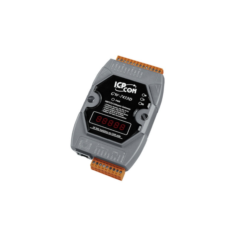

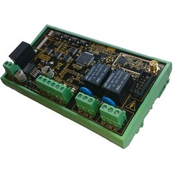
Ethernet Gateway for CANopen networks and Modbus RTU
1 x RJ45 10 / 100Mbps
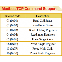
Protocol: Modbus TCP Server
1 x RS232 / RS485 port (non-isolated)
Modbus RTU slave
Baud rate: 1200-115200
1 x CAN port
CANopen
CAN Baud rate: 10K - 1M
Built-in 120 ohm termination
Dimensions: 122 x 72 x 33 mm
Supply voltage : 10 - 30VDC, 2,5Watt
Operating temperature: -25 - + 75 ° C
DIN bracket
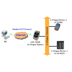
M485-CAN-M-ETH-in module that provides a communications transformation between CANopen protocol and Modbus / TCP RTU protocols. It solves a job-bo representation problem in connecting to an existing CANopen network with an Ethernet Master unit, as long as the Master Unit supports Modbus / TCP protocol.
It allows the CANopen network to be linked to the Internet / Ethernet wherein the remote monitoring and control is achieved. For CANopen network is CAN-M485-M-ETH-In a CANopen master unit. It supports PDO and SDO functions for communication with the slave devices. From the view of Modbus / TCP counter bid / RTU network operates M485-CAN-M-ETH-In a Modbus / TCP server or Modbus / RTU slave role. It can receive commands from Modbus / TCP client or Modbus / RTU master and process the commands to reply or send the related CANopen data. We provide utilities for users to configure the parameters of the CANopen slaves M485-CAN-M-ETH-I. When M485-CAN-M-ETH-In starts up, gathers the necessary information from all slaves that are predefined in the M485-CAN-M-ETH-I using the utility. The figure on the page shows the application architecture for the CAN-M485-M-ETH-I.

Mains adapter - switch mode type
110-240 VAC to 12VDC/1.5A
DC plug: 5.5/2.1 mm
1 meter cable
868MHz Transceiver with 2 x Dry input, 2 x Relay
2 relay outputs, 250VAC/5A, 12V/10A
2 contact inputs, end contact so-called dry contact
Up to 1000 meters in range with gain antenna
Rubber antenna included
Watchdog function
Supply voltage: 12 - 32VDC
RS485 module for 6 Temperature sensors
6-channel RTD input
3-wire RTD input with elimination of wire resistance
Resolution: 16-bit
Individual channel configuration
Disconnected sensor detection
Double Watchdog
Supply: 10 - 30vdc
Operating temperature: -25 to + 75 ° C

Built-in Web server
Web HMI
2 x RJ45 - Daisy Chain
Modbus TCP and Modbus UDP protocols
Good communication security
Dual Watchdog
Operating temperature range: -25 ~ +75 ° C
I / O connection input pair is mirrored to the other's output
3 x Analog input +/- 10VDC, 0 - 20mA (differential)
6 x Digital input with counter
3 x Relay outputs COM, NO

2.8" Touch HMI device with Ethernet and PoE
High Resolution color touchscreen
RTC (Real Time Clock)
GUI design
Modbus TCP/RTU protocol
ESD protection: 4 kV
Operating temperature: -20 ° C ~ 70